CABLEIQ implements a new method to examine the RF transmission performance of cabling to determine if it is qualified for various network types. The current network specifications provide requirements for NEXT and RL and other parameters in terms of traditional frequency domain parameters. There is no distinction between the effects of either distributed or single point coupling or reflection sources. Cabling which has a single point coupling source will generate higher peak to peak coupling noise spikes than cabling with distributed coupling that has the same relative margin relative to the frequency domain limits.
The amplitude of noise generated from distributed sources depends on the nature of how the individual noise signals tunnel back to the receiver and combine. In some cases they may add like a rouge wave or even cancel. In general the effective peak noise is always lower than that generated from a single point source since it is unlikely that all the peaks combine in the worst case. The peak noise from a distributed coupling can be predicted assuming that the noise signals combine randomly and can be treated as uncorrelated events. Since the network requirements make no distinction between the nature of the coupling, it must be able to tolerate the effects of the worst case point source and this can be used as the noise limit requirement.
Using these criteria allows the time domain impulse response of cabling to be examined in order to determine if coupling and reflection noise will be within proper operational limits. Since a single point fault with magnitude at the network frequency domain limit is allowed by the specification, it is used to establish the time domain limit for peak noise. The measured NEXT and reflection impulse responses are then processed in a manner in which information from all time bins is combined statistically using power sum methods (RSS - Residual Sum of Squares) to predict the peak noise that will result from the cable response. The computed statistical peak is then compared to the peak from a single point source to determine if the RF performance is qualified for a specific network type.
This method of qualification generally provides more margin to failure than the traditional frequency domain certification process to limits. The time domain analysis will generally predict failure only when the frequency domain response exceeds the frequency domain limits on average. Single excursions beyond the limit which cause failures in certifications instruments will not result in time domain analysis qualification failures.
Simulations were performed to demonstrate the effect of both point and distributed NEXT sources on the network signaling. The first example assumes a single point NEXT source which has coupling equal to the limit as specified in the 100BASE-TXrequirements. The frequency domain response of this coupling source is shown in figure 1.
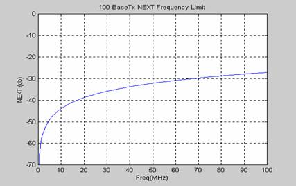
Figura 1: 100BASETX Frequency Domain Channel NEXT Limit
A 100BASE-TX MLT-3 signal was applied to this NEXT coupling function and the time response of the TX and RX response are shown in figure 2. Note the peak coupling of the TX signal is approximately 12 mV for the point source. The noise spikes occur as expected at each transition of the TX signal.
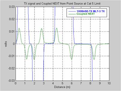
Figura 2: Time Domain of ML3 TX Signal and NEXT Coupled
From Point Source at Channel Limit
A more realistic 3 connector channel is simulated which has -2 dB margin to the Cat 5 frequency limit. The configuration of the channel is shown below. 
In this example, the NEXT has a much more distributed nature. The connectors used in the simulation were at the Cat 5 limit and cable was above the Cat 5 limit for cable. The result is a channel with 2 dB margin relative to the Cat 5 channel limit (over limit). See figure 3 for a graph of the channel frequency domain NEXT characteristics and the Cat 5 Channel limit. This channel would fail normal Cat 5 limits. However, the question that needs to be answered is; does the NEXT peak noise exceed the 12 mV noise level generated by a point source at the channel limit? 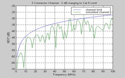
Figura 3: Frequency Domain NEXT for 3 Connector 34 m Channel.
A 100BASE-TX signal was applied to this channel and the coupling to the RX channel was observed. The time domain graph of this simulation result is shown in figure 4. 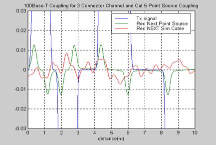
Figura 4: Time Domain Coupling or MLT-3 Signal for Point and Distributed NEXT Conditions The actual coupled signal from the distributed cabling is shown in red. A reference C5 Limit point source is shown in green. The coupling from the Cat 5 point source is 24 mV peak-to-peak and the noise from the TX signal in the channel with distributed coupling is 15 -17 mV peak-to-peak. Although this channel had 2 dB margin relative to the Cat 5 frequency domain limit, the actual noise generated as a result of a 100BASE-TX signal is only 70 % (-3 dB) of that the worst case point source which is allowed by the specification.
This channel will generate less NEXT noise than allowed by the specification even though its frequency domain characteristics exceed the channel limits. This is due to several reasons. On average the NEXT is below the limit for a point source. The second reason is the nature in which the noise combines from the various coupling points. This tends to reduce the effective peak noise level since all individual noise signals dont arrive back at the receiver input at the same time
The preceding examples show the frequency domain magnitude response by itself is not a good predictor of the peak time domain noise that is generated from coupling. All that can be said with regard to the frequency domain data is that if its response is equal to or less then the limit everywhere, then the noise will be within the operational requirements of the network. It provides no indication of how the noise spikes combine. This typically gives a pessimistic evaluation of the actual noise characteristics of the link.
Evaluating the data in the time domain provides a means to predict the actual peak noise characteristics of a link. Figure 5 shows the time domain NEXT response from the CABLEIQ measurement system for the same 3 connector channel in the previous example. The bumps and wiggles in the time response are points of discrete coupling. The actual noise generated on the receive channel will be the combination of all the coupled components as they tunnel back to receiver. The size of the noise that is generated depends on how each individual component combines with the others. 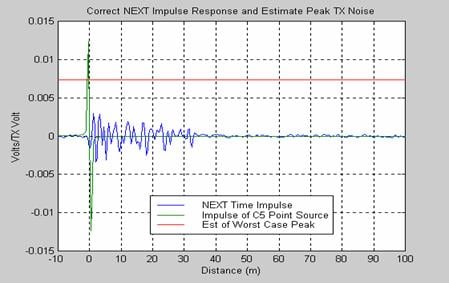
Figura 5: CABLEIQ Time Domain NEXT of 34 Meter Channel and Predicted Peak Noise The time domain NEXT response was processed to estimate the peak noise. This estimate is shown as a flat straight red line. The estimate peak is 7,5 mV which is very close to the 8 mV peak seen when the actual 100BASE-TX signal is applied to the same channel. The coupling from a single point source at the connector limit is shown in green to provide a reference for the qualification limit. Note the predicted peak noise coupling from the channel with distributed NEXT is significantly less than the point source as demonstrated in the previous simulation results. Therefore the RF characteristics of this channel would be qualified for 100BASE-TX even though the frequency domain response had negative margin in one area of the sweep.
This example shows that the time domain NEXT response of the channel can be evaluated and a good prediction of the peak noise resulting from coupling can be made. This prediction of the peak coupled noise level can then be compared to the noise level allowed for a single point source to determine it the transmission parameters qualify for transmission of a specific network type.
One issue with this method of qualification testing is that typically it will be more optimistic than the frequency domain certification testing to specific limits. Most cables that fail certification tests will pass the CABLEIQ qualification tests. The CABLEIQ does a time domain analysis to ensure the peak coupled noise is within the required limits. This processing takes into account the actual manner in which the coupling combines and therefore is more lenient. | 

