SC/APC to SC/APC fiber testing with the SimpliFiber Pro
The following article describes how to test an SC/APC to SC/APC fiber link using TIA/EIA Method A.1 for Singlemode. Since APC is typically used on Singlemode only, this article does not address Multimode APC applications.
The rule: "You cannot put an SC/APC connector in the Output port of the source, but you can put an SC/APC connector in the Input port of the meter."
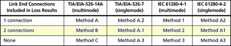
You may hear people referring to this as the "1 jumper method". To confuse matters, the IEC Standards call it Method 2 for Multimode and Method A1 for Singlemode, as shown in the table below:
These connectors have typically been reserved for long haul telecoms. In this environment, high power lasers are used which are very sensitive to reflections. Severe reflections can destroy the laser. So what is different about the APC? A slight angle is introduced on the curved ends.
UPC: Ultra Physical Contact
The most common types of fiber connectors are PC and UPC (ultra physical contact). With UPC, the fiber ends are more rounded than the PC finish giving greater contact between the glass surfaces.
The rule: "You cannot put an SC/APC connector in the Output port of the source, but you can put an SC/APC connector in the Input port of the meter."
You may hear people referring to this as the "1 jumper method". To confuse matters, the IEC Standards call it Method 2 for Multimode and Method A1 for Singlemode, as shown in the table below:
These connectors have typically been reserved for long haul telecoms. In this environment, high power lasers are used which are very sensitive to reflections. Severe reflections can destroy the laser. So what is different about the APC? A slight angle is introduced on the curved ends.

UPC: Ultra Physical Contact
The most common types of fiber connectors are PC and UPC (ultra physical contact). With UPC, the fiber ends are more rounded than the PC finish giving greater contact between the glass surfaces.

- Power on the SimpliFiber Pro Source.
- Press the AUTO key on the SimpliFiber Pro Source .
- In AUTO mode, the SimpliFiber Pro Source will tell the SimpliFiber Pro meter which wavelength it is transmitting at. This allows both wavelengths to be measured at the same time.
- Leave the SimpliFiber Pro Source to stabilize for at least 5 minutes.
- While the SimpliFiber Pro Source is stabilizing, clean and inspect your test reference cords.
- Connect your test reference cord as shown below, making sure SC/APC is inserted into the Input port.
- Press the Mode key until you see LOSS in the upper right hand screen (shown below).
- Press the F3 key once to set the reference. When you see OK appear, the reference has been set for both wavelengths.
- If the SimpliFiber Pro Source has been allowed to stabilize fully, you should see 0,00 dB as shown below:
- If you start to see it change from 0,00 dB, it means the SimpliFiber Pro Source has not been allowed to stabilize. Wait until the reading stabilizes, then press the F3 key again to reset the reference.
- Remove the reference patch cord from the INPUT PORT ONLY on the SimpliFiber Pro meter.
- Put a known good SC/APC to SC/APC test reference cord into the INPUT port on the SimpliFiber Pro Meter.
- Connect to the fiber link to be tested.
- The SimpliFiber Pro Meter will then automatically measure the loss at both wavelengths.
- Press the F1 key to save the test result. It will save both wavelengths automatically as one record. For more information on calculating loss budgets - click here. If you are testing against for a specific application - click here.


