BICSI Wrap Up: Top 3 Questions Asked
February 14, 2018 / General, 101 learning, Best Practices
It’s always interesting at trade shows to learn what’s on the minds of end users, designers and technicians alike when it comes to testing. And this year’s BICSI Winter Conference was no different.
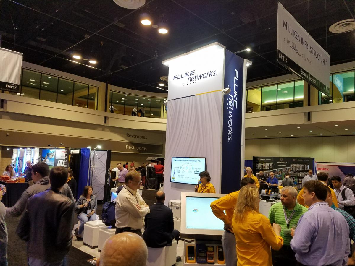
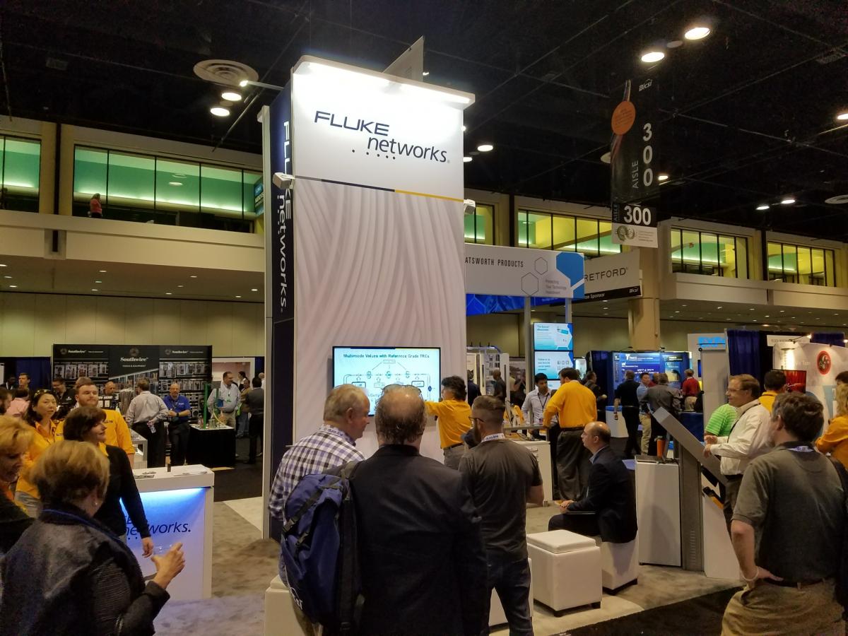
If you were one of the more than 4,000 attendees at last week’s show in Orlando, maybe you gained 3 CECs in Monday’s pre-conference seminar Testing - High Speed Fiber Links featuring our own Jim Davis and other industry experts, or maybe you saw Jim Davis present Field Testing and Troubleshooting of PON LAN Networks Per IEC 61280-4 on Wednesday morning. Or maybe while wandering the exhibit hall, you simply stopped by the Fluke Networks Booth #309.
Regardless of your level of participation, we thought we’d take a minute to highlight what seemed to be the most common questions our experts encountered last week in sunny Florida.
So How Does One Test HDBaseT?
With several seminars and presentations at the 2018 BICSI Winter Conference, including a preconference seminar on HDBaseT installation by the HDBaseT Alliance and Belden’s presentation on Wednesday on HDBaseT vs. AV over IP, you can imagine HDBaseT was on the minds of several conference goers.
HDBaseT transmits uncompressed HD video, audio, 100BaseT Ethernet data, power and various control signals over common category copper cabling up to 100 meters. The main difference between HDBaseT and Ethernet is in the protocol itself—HDBaseT is not packet-based IP data. But there is plenty that stays the same.
Since HDBaseT runs over the same cabling as the LAN, it is deployed in the same way, includes distance limitations and can be impacted by crosstalk just like an Ethernet system. And while there are tools for testing proper resolution and frame rate, another similarity between HDBaseT and Ethernet systems is that the cabling plant still needs to be tested for compliance with the appropriate TIA standard. So if Category 6A cable is deployed for an HDBaseT system, you can certify it using your Fluke DSX Series CableAnalyzer to make sure you get your warranty.
Does Fluke Test Passive Optical Networks and APC Connectors?
Those attendees who asked this question probably didn’t make it to Jim’s presentation on Wednesday Morning, so we thought we’d take a moment to answer this question with an emphatic, “Yes!”
Just like any fiber optic system, passive optical networks (PONs) require insertion loss testing. And this can be easily done with Fluke Networks’ CertiFiber® Pro. But as an application that uses multiple wavelengths over a simplex singlemode fiber and APC style connectors, there are some things you should know.
Since PONs use three different wavelengths– 1310nm for upstream transmission, 1490nm for downstream and 1550nm for RF video—you’ll want to make sure you test the system at both the 1310 and 1550nm wavelengths. If both pass, you can rest assured that 1490nm will also pass. You also need to know what your maximum insertion loss should be, and for PONs, it’s a minimum of 13 dB and a maximum of 28 dB.
And yes, we have the capability to test APC connectors. The CertiFiber Pro accepts APC connectors in the INPUT port because it is a non-contact mating. This design feature allows you to set a 1 jumper reference for SC, ST, FC, SC/APC and LC/APC fiber testing. However, the OUTPUT port that makes physical contact with the test reference cord uses a UPC connector so you’ll need hybrid UPC to APC and APC to APC cords when testing. Click here to learn more and stay tuned for more blogs on PON testing.
How Do You Test PoE?
When it comes to testing PoE where DC power is delivered simultaneously with data, the key performance parameter you want to test for (even if the standards don’t require it) is DC resistance unbalance. You see, PoE is transmitted by applying a common-mode voltage that is evenly split between each conductor of a pair, and to achieve this, the DC resistance of each conductor in the pair must be balanced.
Any difference in resistance between two conductors is referred to as DC resistance unbalance. When this difference is too high, it can distort the waveforms of Ethernet data signals. And what good is delivering PoE to power an 802.11ac Wi-Fi access point if the data signal transmission experiences bit errors or completely malfunctions?
IEEE Std 802.3bt specifies a maximum DC resistance unbalance of 3% between conductors in a pair and a maximum DC resistance unbalance of 7% between any two pairs. Thankfully Fluke Networks DSX Series CableAnalyzers can quickly test DC resistance, DC resistance unbalance within a pair and DC resistance unbalance between pairs. And since this testing adds little additional time to a standard test, it is highly recommended—it’s the only way to be truly sure that the installed system will meet the latest PoE requirements.
For more information on testing high power PoE cabling systems, BICSI members can check out the upcoming March/April issue of BICSI’s ICT Today publication. And to find out how industry leaders Fluke Networks, Legrand, and Superior Essex have joined up to create a line of standard compliant products in accordance with DC resistance requirements, click here to download the whitepaper.
And thanks for visiting us at BICSI!

