Cable Testing 101: There's No Gain with "Gainers"
October 13, 2016 / General, 101 learning, Installation and testing, Upgrading and troubleshooting, Best Practices

Akin to water flowing from a small pipe into a large pipe, gainers are essentially perceived increases in optical power that occur at splice points due to variations in fiber characteristics, including core diameter, numerical apertures, mode field diameters and backscatter coefficients.
Since gainers can be a significant source of confusion for new optical time domain reflectometer (OTDR) users, let's take a look at why these occur, what impact they have and how to avoid them.
What are the Causes?
Gainers can show up when using an OTDR to measure loss from one end of a fiber link, and they occur due to the way in which an OTDR measures reflected light along the length of the fiber. An OTDR assumes that fiber characteristics such as core and cladding size are consistent along the length with no variations, and it calculates signal loss based on the amount of reflected light, or backscatter, that it detects.
But even if two connected fibers are the same type of fiber, they may not necessarily be cut from the same length of fiber so variations can still occur, including different backscatter coefficients (a fancy term for information about the relative backscatter level of the fiber). And that means that the fiber used for the launch and receive cords of the OTDR may also have a different backscatter coefficient than the fiber under test.
Different backscatter coefficients can cause more light to be backscattered after a connection than before the connection, causing the OTDR to show a loss value that is less than it actually is--a gainer.
Why Is It a Problem?
The term "gainer" makes it seem like you are actually gaining something, and you might think that ending up with a lower than actual loss value is a good thing. Think again. Gainers ultimately don't gain you anything but headaches and increased cost.
When loss results are lower than they actually are, you might be under the misconception that there is plenty of headroom to add another connection point, extend the distance or simply guarantee performance. But gainers are false positives that when taken as true, can result in the fiber link ultimately not supporting the application.
For example, an OM4 150-meter channel has a maximum channel loss of 1.5dB to support 40 gigabit per second speeds (40GBASE-SR4). If you're measured loss comes in at 1.3dB, you might think it's okay to add another 0.2dB connector. But what if your measured loss includes a gainer, and the actual loss of the channel is really closer to 1.4dB? Now you end up with a customer asking you to come back and troubleshoot the installation to determine why they're not getting the data rate they should.
How Do You Prevent It?
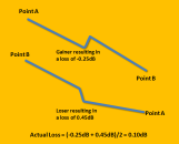
Preventing gainers from impacting the quality of your installation is actually quite simple. That's because wherever there's a gainer, there's a loser. That's right. While transmitting in one direction may cause the gainer, when the measurement is taken in the other direction where less light is backscattered after the connection, the measured loss is greater than the actual loss.
The simple solution, and the one required by industry standards, is to measure in both directions--otherwise known as bidirectional testing. As shown here, when the OTDR trace with the gainer is averaged with the trace of the loser, the result is the actual loss.
Fluke Networks makes this even easier. To reduce the cost and time involved in measuring from both ends, our OptiFiber® Pro or DSX-5000 CableAnalyzer™ Pro feature a built-in “SmartLoop” Assistant that uses a loop at the remote end of a duplex fiber link, allowing you to test in both directions from one end. It also features on-board averaging of the two measurements to provide an accurate final loss measurement.
Publicaciones recientes Ver todas >
¿Qué es la fibra óptica? Una guía
20-3-2024
Más publicaciones generales Ver todas >
¿Quiere actualizarse a Wi-Fi 6?
06-1-2025


©2006-2021 Fluke Corporation。保留所有权利。
RM2011, 20/F, SCITECH Tower, 22 Jianguomenwai Avenue, Chaoyang District, Beijing, China
地址:北京市朝阳区建国门外大街22号赛特大厦20层2011室
联系电话:400-8103435
沪ICP备11037028号-15![]()