An Update on IEC 61280-4-1 Edition 3, Multimode Attenuation Measurement of Installed Cabling Plant
June 25, 2020 / General, Standard and Certification
Introduction
IEC and other organizations, such as TIA, routinely reaffirm standards every few years. Reaffirmation is a way for subcommittees to decide if a standard is “dated” or still applicable to current times. Technology and market needs change often which drive standards to change. IEC 61280-4-1 edition 2 was in such a cycle several years ago and it was decided an edition 3 was needed.
The important changes found in the 2019 Edition 3 publication are the inclusion of the equipment cord method, information on uncertainty, guidance on the use of bend insensitive multimode fiber in test cords, and an analysis of measurement bias when using reference grade test cords. As a side note, TIA has an equivalent testing standard (TIA-526-14-C) which is an adaption of IEC 61280-4-1 Edition 2. TIA prefers to adopt Edition 3 as TIA-526-14-D.
Channel Testing
Since Edition 2 was published, there was interest in defining a test method for a channel. Unlike copper testing, a channel test method for fiber did not exist. Fiber certification testing is only defined for a permanent link so why test the channel? Testing a permanent link doesn’t necessarily guarantee that an IEEE application will work. When it doesn’t, an installer might want to test the channel. The test is really used for troubleshooting and includes the customer equipment cords – the equipment cords attach between the permanent link and the transceivers on each end. In IEC 61280-4-1 Edition 3, channel testing is called “the equipment-cord method” instead of the channel test method. The channel test method was first introduced in another group – ISO/IEC JTC 1/SC 25/WG 3 and seems to be that group’s “property”.
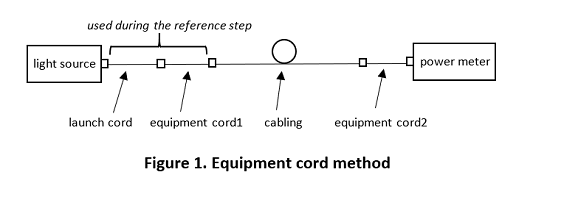
The initial reference is set with the test vendor’s 2-meter test reference cord and the customer’s equipment cord 1, acting as a complete launch cord, when plugged into the power meter. The reference step uses a derivative of the 1-cord method. For the cabling test, instead of the test vendor’s receive cord, which is normally attached between the cabling under test and the power meter, a second equipment cord 2 is used (see Figure 1). Since this is a one-off troubleshooting test, it can only be used for a unique channel that will use those specific equipment cords. As you can see, the equipment-cord method is not the type of test that you would want to use often because a new reference is needed for every channel tested.
Uncertainties
A complete analysis of uncertainties is included in Edition 3. Prior to the introduction of high-speed applications, multimode attenuation testing of installed cabling did not suffer the tight (low value) attenuation limits. Now that budgets and test limits are low, certification testing has gotten more stringent. That is, test reference cords are needed, well controlled light launch conditions are mandated, and high uncertainty is not tolerated. Imagine testing and certifying a link where the test limit is 1.9 dB.
Edition 3 gives many examples of uncertainties for various cabling lengths using any of the four test methods with a light source/power meter. These methods are the 1-cord, 2-cord, 3-cord, and equipment-cord methods. One of the important takeaways when examining the uncertainty tables in edition 3 is to make sure to use the test vendors’ reference grade test cords. Fluke Networks supplies test reference cords that use reference grade fiber and connectors. Reference grade means the tolerances on components are well controlled.
Bend Insensitive Fiber in Test Cords
The first draft of IEC 61280-4-1 Edition 3 added subdivisions A1-OM2a for traditional macrobend attenuation fiber and A1-OM2b for bend-insensitive performance (BIMMF). Originally, the test reference cords stated that non-BIMMF shall be used in test cords. With subsequent drafts, this requirement was first relaxed to state that non-BIMMF should be used in test cords then expanded to allow either non-BIMMF or BIMMF to be used in test cords.
There is now evidence that testing installed cabling with either non-BIMMF or BIMMF produces equivalent attenuation measurements. However, there is still data showing that verification of test cords using BIMMF can produce routinely lower attenuation values than when testing non-BIMMF. While it appears non-BIMMF and BIMMF are interchangeable in cabling, testing short lengths of fiber using BIMMF test cords can produce misleading results. As a result of this ambiguity, Fluke Networks continues to supply test cords with non-BIMMF and will continue to do so. Fluke Networks has found that test reference cords that use non-BIMMF consistently produce results with the lowest uncertainty.
Launch Conditions
The only notable change in the encircled flux Annex is the change to “attenuation variation coefficient” for 1300 nm with 50 µm fiber. This was changed to 0.20 dB. This is a requirement that provides guidance for the test equipment suppliers rather than for the user. Incidentally, the modeling used to determine the encircled flux limits was based on near field measurements of non-BIMMF.
Test Reference Cords and Measurement Bias
If you think about it, attenuation testing of installed cabling using test equipment is a way to quantitatively measure performance. However, it is still a substitute method to predict network performance. Reference grade terminations are used in test cords to reduce measurement uncertainty. If an off-center connector was used in a test cord, the test result would depend on the orientation of the test cord to the cabling under test. If a reference grade connector was used in a test cord, the measured attenuation of the cabling will be less than if a standard grade test cord was used. This difference is defined as a measurement bias. The details can be found in Annex I in Edition 3.
Annex I provides values for standard grade, reference grade, and mixed grade connections and continues to explain the impact of using reference grade test cords when using either a light source/power meter or OTDR. Examples are also given for calculating attenuation limits.
Additional Guidance
Standards take time to complete, usually 2 to 3 years, for several reasons. One reason is because it is difficult for a diverse group of participants representing the fiber industry for components and testing to reach consensus. Although IEC 61280-4-1 Edition 3 includes guidance on less common 62.5/125 µm, it is really included for installers testing older legacy installations sometimes referred to as the “installed base”. However, the reality is new installations should only be using 50/125 µm bend insensitive multimode fiber while running only at 850 nm so 62.5/125 µm is not recommended.
Since Fluke Networks’ multimode light sources and test cords can accommodate testing installed optical fiber at 50/125 µm, and 62.5/125 µm, and 850/1300 nm wavelengths, we can support older and new installations. As stated previously, the test cords used with the Fluke Networks equipment uses non-BIMMF and can be used to test either BIMMF or non-BIMMF installations successfully and accurately.


